Flame Arresster
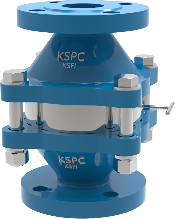
KSFI TYPE
The model KSFI Inline Flame Arrester is designed, manufactured, tested according to API 2000, British Standard Specification Code BS7244, and EN 12874 / ISO 16852. The units are passive devices with no moving parts. They prevent the propagation of flame from the exposed side of the unit to the protected side by the use of a 316L stainless steel crimped metal ribbon type flame cell element. This construction produces a matrix of uniform opening that are carefully constructed to quench the flame by absorbing the heat.>>>>>Data sheet
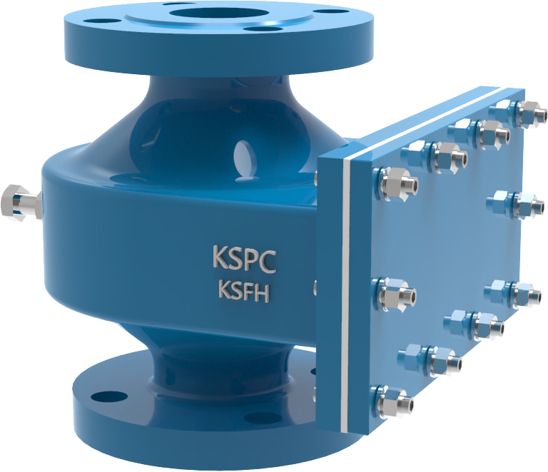
KSFH TYPE
The model KSFH Inline Flame Arrester is designed, manufactured, tested according to API 2000, British Standard Specification Code BS7244, and EN 12874 / ISO 16852. Additionally All most of size shall be approved FM (Factory Mutual). The units are passive devices with no moving parts. They prevent the propagation of flame from the exposed side of the unit to the protected side by the use of a 316L stainless steel crimped metal ribbon type flame cell element. This construction produces a matrix of uniform opening that are carefully constructed to quench the flame by absorbing the heat.>>>>>Data sheet
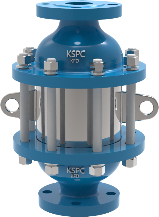
KFD TYPE
The model KFD inline detonation flame arrester is designed, manufactured and tested according to API 2000, British Standard Specification Code BS7244, EN 12874 / ISO 16852 & USCG, IMO MSC/Circ.677. The KFD detonation flame arresters provide protection against flame propagation in piping systems that are manifolded or have long runs. The arresters are designed to stop an ignited flammable vapor mixture traveling at subsonic or supersonic vapor velocities. They are also designed to protect against continuous burning against the 316LSS flame cell for a specific period.>>>>>Data sheet
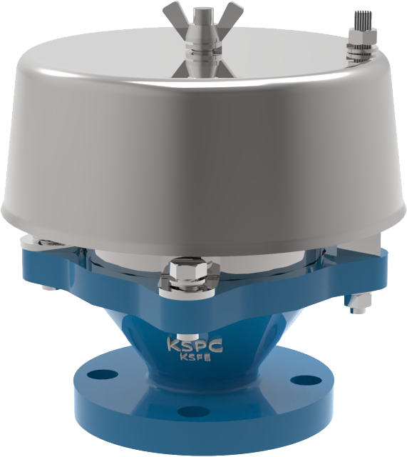
KSFE TYPE
The KSFE flame arrester are designed, manufactured and tested according to API2000, BS7244 (British Standard Specification), and EN 12874 / ISO 16852. The units allow free venting in combination with flame protection for vertical vent applications. They prevent flame propagation by absorbing and dissipating heat using spiral wound crimped ribbon 316LSS flame cells.>>>>>Data sheet
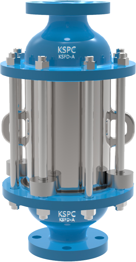
KSFD-A TYPE
The model KSFD-A inline detonation flame arrester is designed, manufactured and tested according to API 2000, British Standard Specification Code BS7244, and EN 12874 / ISO 16852. The KSFD-A detonation flame arresters provide protection against flame propagation in piping systems that are manifolded or have long runs. The arresters are designed to stop an ignited flammable vapor mixture traveling at subsonic or supersonic vapor velocities. They are also designed to protect against continuous burning against the 316LSS flame cell for a specific period.>>>>>Data sheet