Breather Valve
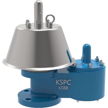
KSBB/BS TYPE
The model KSBB and KSBS pressure vacuum valves are an advanced design for vent to atmosphere applications. Designed manufactured and tested according to the API 2000 code, these valves utilize the latest technologies to provide protection against positive or vacuum over pressure and prevent air intake, evaporative losses of product and help to contain odorous and potentially explosive vapor.>>>>> Datasheet
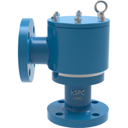
KSBD/DS TYPE
The model KSBD and KSDS pressure vacuum valves are an advanced design for pipe away applications. Designed manufactured and tested according to the API 2000 code. Utilize the latest technologies to provide protection against positive or vacuum over pressure and prevent air intake, evaporative losses of product and help to contain odorous and potentially explosive vapours.>>>>>Datasheet
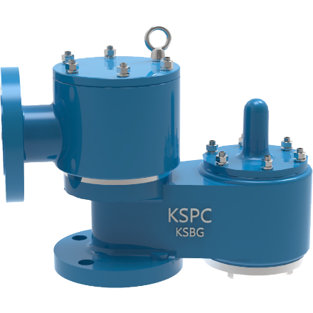
KSBG/GS TYPE
The model KSBG and KSGS pressure vacuum valves are an advanced design for pipe away applications. Designed manufactured and tested according to the API 2000 code, these valves utilize the latest technologies to provide protection against positive or vacuum over pressure and prevent air intake, evaporative losses of product and help to contain odorous and potentially explosive vapours.>>>>>Data sheet
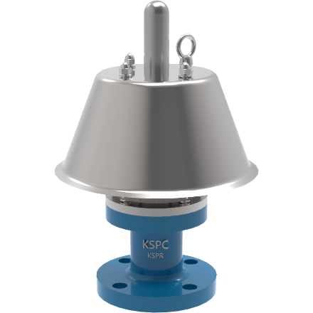
KSPR/PS TYPE
The model KSPR and KSPS pressure vacuum valves are an advanced design for vent to atmosphere applications. Designed manufactured and tested according to the API 2000 code. Utilize the latest technologies to provide protection against positive or vacuum over pressure and prevent air intake, evaporative losses of product and help to contain odorous and potentially explosive vapours.>>>>>Data sheet
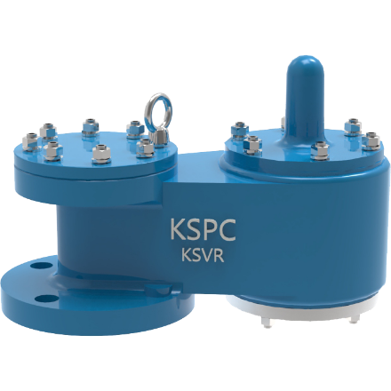
KSVR/VS TYPE
The model KSVR and KSVS are designed manufactured and tested according to the API 2000 code. Utilize the latest technologies to provide protection against positive or vacuum over pressure and prevent air intake, evaporative losses of product and help to contain odorous and potentially explosive vapours.>>>>>Data sheet
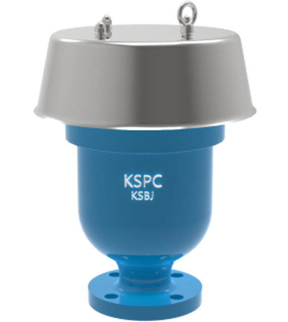
KSBJ TYPE
The model KSBJ is designed to release accumulated air pockets from the system, while pressured pipelines. Air pockets increase energy consumption because pumping operation will be at higher water heads to overcome pressured air. KSBJ has function to protect high shock and surge pressure, water hammer and liquid overfl ow from fresh or sea water pipelines. KSBJ air release valve can provide low cast insurance to protect expensive maintenance cost of pipelines and pump systems.>>>>>Data sheet